Errors in events analysis
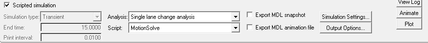
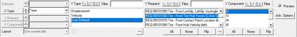
I'm carrying out a constant radius analysis and have changed the hard points only, given the following input for the analysis
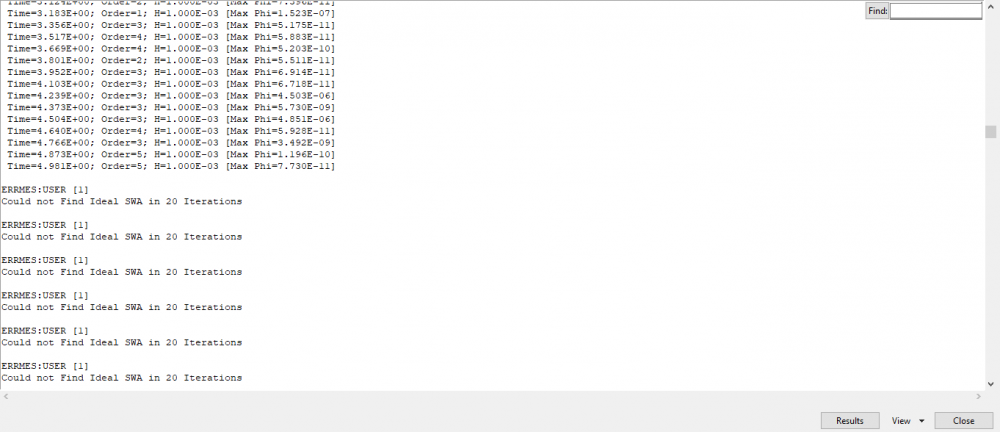
the errors that I'm getting is
ERROR: At time=1.401E-08 the integrator failed to proceed.
----------- Possible Causes -----------------------------------------------------
(1) The integration has become unstable. Tighten (decrease) integr_tol, h_max,
or both in Param_Transient can help stabilize the integration. If the simulation
contains distinctive phases, use multiple Simulate, each with its
own proper integrator parameter setting, to selectively tighten the tolerance
during the period where instability is encountered.
(2) If the simulation was terminated because stepsize has diminished consistently
below h_min, reduce h_min in Param_Transient to force integration to continue.
(3) Non-physical inertia properties, such as mass=100 Kg and Ixx=Iyy=Izz=1 Kg*mm^2,
or extremely small inertia on a part with an unconstrained degree of freedom.
Make sure the modeling data, in particular the part inertia and the gravity, are
specified in proper units consistent with the units given in Param_Unit element.
(4) Beam, flexible body goes out of linear range, bushing has large rotation along
more than one axis, curve goes out of its interpolation range, higher-pair joint
goes out of the range of U or V, etc. Make sure fundamental modeling assumptions,
such as rigid contact assumption used in Force_Contact, are not violated.
(5) Motion displacement defined using LINSPL, AKISPL in dynamic analysis, or as a
function of model states (DX, VX etc), as well as forces defined as a function of
other forces, can cause hard convergence and integrator failure. Avoid these
modeling practices wherever possible.
---------------------------------------------------------------------------------
ERROR: Abnormal return from transient analysis
Answers
-
Hi Adrian,
Looking at this message only without knowing the model is not possible to identify the error.
Does MS write a .h3d animation? Did you check if it is ok during statics?
When changing the hard points, did you keep the symmetry making sure left and right are correct?
Maybe you could upload the model.
Best regards,
Felipe.
0 -
If you only changed hardpoints, without updating mass information, spring rates, and spring preload, etc, it's possible that your vehicle is not built in a way to expect reasonable initial conditions. Since the simulation is failing right at time t=0, this is the most logical explanation based on the info you have provided.
A common practice is to build half-car models before building a full vehicle model. Then we run the half-car models through basic analysis like static ride, or Kinematics and compliance, to ensure the model is robust, and has the correct corner weights on the wheels, etc. Then, when we assemble the full vehicle model, there is a highly likelihood that the model will run successfully.
Also, it is better to run more basic, open loop analysis before constant radius. I will usually run straight line acceleration as my first full vehicle event. Starting with simpler events also assists with debugging the initial model.
Chris
0 -
Hello Felipe
Yes, it does write a .H3D file and it has a default option for transient, I don't know how you could change it to static.
Yes, the model is symmetric and the spring stiffness and preload and mass inputs are given.
How do I calculate the moment of inertia, do we calculate it about the body's origin OR from the CG of the vehicle.
Can you please send me your private file sharing link and will it be confidential?.
0 -
I'm getting these errors when I carry out a static ride analysis on transient mode and have set the weight of the components and spring stiffness and changed the hardpoints for it.
ERROR: GTCMAT not supported during dynamic analysis, it will be set to zero!
ERROR: GTCMAT not supported during dynamic analysis, it will be set to zero!INFO: Analysis model processed.
Partitioning generalized coordinates...
INFO: Total Number of Independent Coordinates = 54
Generalized coordinates partitioned. Continue with initializing model...INFO: Number of Total Entries in Residual Vector: 3240
INFO: Number of Non-zero Entries in Jacobian Mtx: 20751 (0.197674% Filled)
INFO: Number of Entries Associated with VarCoord: 38 (0.183124%)WARNING: NaN encountered from User-Request/80000040:Component/4! Future warnings will be suppressed.
WARNING: NaN encountered from User-Request/80000050:Component/6! Future warnings will be suppressed.
WARNING: NaN encountered from User-Request/80000080:Component/2! Future warnings will be suppressed.
WARNING: NaN encountered from User-Request/80000110:Component/3! Future warnings will be suppressed.
WARNING: NaN encountered from User-Request/80000180:Component/8! Future warnings will be suppressed.
WARNING: NaN encountered from User-Request/80000190:Component/8! Future warnings will be suppressed.
WARNING: NaN encountered from User-Request/80000200:Component/3! Future warnings will be suppressed.
WARNING: NaN encountered from User-Request/80000210:Component/7! Future warnings will be suppressed.
WARNING: NaN encountered from User-Request/80000220:Component/6! Future warnings will be suppressed.
WARNING: NaN encountered from User-Request/80000270:Component/2! Future warnings will be suppressed.
WARNING: NaN encountered from User-Request/80000310:Component/2! Future warnings will be suppressed.
WARNING: NaN encountered from User-Request/80000320:Component/2! Future warnings will be suppressed.
WARNING: NaN encountered from User-Request/80000330:Component/2! Future warnings will be suppressed.
WARNING: NaN encountered from User-Request/80000340:Component/2! Future warnings will be suppressed.
WARNING: NaN encountered from User-Request/80000350:Component/2! Future warnings will be suppressed.
Starting dynamic analysis. . .DYNAMIC SIMULATION PARAMETERS
----------------------------------------
Start Time : 0.000E+00
End Time : 1.000E+01
Print Interval : 1.000E-01Integrator : DSTIFF
Error Tolerance : 1.000E-03
Maximum Step Size : 1.000E-02
Minimum Step Size : 1.000E-06
DAE Index : 3
DAE Constraint Tolerance : 1.000E-05Time=6.250E-04; Order=1; H=6.250E-04 [Max Phi=1.178E-07]
Time=1.034E+00; Order=4; H=1.000E-02 [Max Phi=1.455E-07]
Time=2.034E+00; Order=4; H=1.000E-02 [Max Phi=4.095E-10]
Time=3.034E+00; Order=4; H=1.000E-02 [Max Phi=9.240E-12]
Time=4.034E+00; Order=3; H=1.000E-02 [Max Phi=7.403E-12]
Time=5.134E+00; Order=3; H=1.000E-02 [Max Phi=3.867E-12]
Time=6.134E+00; Order=3; H=1.000E-02 [Max Phi=4.594E-12]
Time=7.134E+00; Order=2; H=1.000E-02 [Max Phi=2.558E-12]
Time=8.134E+00; Order=3; H=1.000E-02 [Max Phi=5.457E-12]
Time=9.134E+00; Order=3; H=1.000E-02 [Max Phi=4.775E-12]
Time=1.000E+01; Order=3; H=5.625E-03 [Max Phi=2.111E-12]DAE SOLVER STATISTICS (DASPK-Index3)
------------------------------------------------
Number of solution steps = 1013
Number of residue evaluations = 1083
Number of jacobian computations = 8
Number of error test failures = 2
Number of nonlinear convergence failures = 0and then created a H3D file in which the jacks did not move.
0 -
The static ride analysis contains user subroutines that rely on running a static analysis. You should run the static ride analysis as a static solution, not transient.
If you can switch off all of the outputs that rely on user subroutines, you and probably get the analysis to run, but this really isn't the purpose of the static ride analysis event.
0 -
Altair Forum User said:
If you only changed hardpoints, without updating mass information, spring rates, and spring preload, etc, it's possible that your vehicle is not built in a way to expect reasonable initial conditions. Since the simulation is failing right at time t=0, this is the most logical explanation based on the info you have provided.
A common practice is to build half-car models before building a full vehicle model. Then we run the half-car models through basic analysis like static ride, or Kinematics and compliance, to ensure the model is robust, and has the correct corner weights on the wheels, etc. Then, when we assemble the full vehicle model, there is a highly likelihood that the model will run successfully.
Also, it is better to run more basic, open loop analysis before constant radius. I will usually run straight line acceleration as my first full vehicle event. Starting with simpler events also assists with debugging the initial model.
Chris
What do you mean by model being robust and correct weight on the wheels?
I have also carried out the Static ride and K&C and have got the results.
should I carry the same process with the rear and then carry on with the full car assembly?
0 -
How do I calculate the moment of inertia, do we calculate it about the body's origin OR from the CG of the vehicle.
0 -
Under Tools -> CG/Inertia summary, MotionView can calculate the overall CG and moment of inertia of your model. It is typically calculated about the origin, but you can calculate it with respect to another reference frame if you need to.
0 -
Thank You
I have done the straight line braking analysis with only setting the hard points, mass and the event parameters and default moment of inertia values.
But, during the constant radius analysis the car takes a turn in the wrong direction as shown in the below attachments.
How do we control the steering inputs, do we need to use advance driver?
Which are the input data that affect my results?
We are getting values for the MOI from the above instructions given by Chris Coker, can using those values lead to correct results?
<?xml version="1.0" encoding="UTF-8"?>
0 -
If the steering wheel is steering in the correct direction (it is unclear in the screen shot), but the road wheels are steering in the wrong direction, then the coupler that defines the steering gear needs to have it's sign changed.
This sign convention is usually sorted out when you review the animation from your front suspension K&C analysis.
Edit: Upon reviewing the screen shot more closely, it's clear that your steering rack is in front of the wheel centerline. In the default model, the steering rack is positioned behind the rear wheels. This explains why your vehicle is steering in the opposite direction (assuming you did not update the steering coupler sign when you updated hardpoints).
0 -
Thank you, changing the sign for the coupler solved it.
1) While simulating for the single lane change, the car used to not complete the full track according to specified speeds . So I altered the track length by changing the formula in segment distance which is[ 1000*sqrt(ds_lane_chg.lat_span.value^2+ds_lane_chg.long_span.value^2)] to (800*sqrt.....) and (500*sqrt...) which reduced the track length. But then the steering wheel became irresponsive when it enters the lane and later approx while exiting the lane becomes responsive and starts to turn as shown in the attachments.
How can I change the time for the simulation which is 6 seconds also the Lateral 0.5G can it be change to a higher value to take sharper lane changes.
2) I wanted to simulate the vehicle going down a slope so I altered the single lane change points (outline points 5,6,7,8). But the vehicle continued to move in the straight line only. shown in the attachments
Is it possible to do it this or can any changes be done to make it follow the track or templates be created for such specific events.
also can the following load output request be created for it or copying the properties from different output request from other analysis be the solution ?
3) As suggested above for the moment of inertia, the value that are used for computing the analysis are taken from the data summary (where I will have to update it to the values given in CG/Inertia summary ) or from the tool>CG/inertia summary value are taken directly for computing.
Which Values do I use and do I update it in the data summary.
How do I change the reference frame from global frame.
<?xml version="1.0" encoding="UTF-8"?>
0 -
1. To change the end time of the simulation, you will need to edit the template. To increase the lateral acceleration, you can increase the speed of the vehicle.
2. The lane change is intended to be used with a flat road. If you need to run a non-flat road, you will need to change the road definition file. Note, some tire models are not compatible with non-flat roads, or require additional licensing depending on which tire model you are using. The Altair Driver has a path follower event that will work better for this kind of event, if you need to run something other than a lane change.
3. To change the reference frame to something other than global, when using the CG/Inertia summary, you need to be using HyperWorks version 2019 or later.
0 -
Thank you
1. I have changed the end time to 15, yet the simulation goes on only for 6 sec.
2. I have entered the values obtained from Tools>CG\Inertia Summary>Moment of inertia into Model>Data Summary>Bodies and getting this error.
Also does adding these values lead to more accurate results?
STATICS SIMULATION COMPLETED
Deactivate MOTION/115002
Deactivate MOTION/215002
Deactivate MOTION/115003
Deactivate MOTION/215003
Deactivate JPRIM/303001
Deactivate JPRIM/303002
Execute Modify Command...
ORIGINAL:
<Motion_Joint id='315001' expr='0'/>
MODIFIED:
<Motion_Joint id='315001' expr='VARVAL(31500100)'/>
INFO: Starting SMP run with up to 4 threads.
WARNING: Error in principal J for body [id=10505]: Ji+Jj<Jk!
J=(2746.05, 254064, 280604) in body CG principal inertia frame.
Execution continues but the results, if dynamic analysis, may be incorrect!
WARNING: Error in principal J for body [id=20505]: Ji+Jj<Jk!
J=(2746.05, 254064, 280604) in body CG principal inertia frame.
Execution continues but the results, if dynamic analysis, may be incorrect!
WARNING: Error in principal J for body [id=11405]: Ji+Jj<Jk!
J=(10487.3, 455235, 584910) in body CG principal inertia frame.
Execution continues but the results, if dynamic analysis, may be incorrect!
WARNING: Error in principal J for body [id=21405]: Ji+Jj<Jk!
J=(10487.3, 455235, 584910) in body CG principal inertia frame.
Execution continues but the results, if dynamic analysis, may be incorrect!Calling RELSUB in DLL [mbdtire]...
INFO: Analysis model processed.Partitioning generalized coordinates...
INFO: Total Number of Independent Coordinates = 133
Generalized coordinates partitioned. Continue with initializing model...INFO: Number of Total Entries in Residual Vector: 6365
INFO: Number of Non-zero Entries in Jacobian Mtx: 43487 (0.10734% Filled)
INFO: Number of Entries Associated with VarCoord: 3094 (7.11477%)
Solving Initial Velocity...
INFO: Initial velocity solution converged in 2 iterations.Starting dynamic analysis...
DYNAMIC SIMULATION PARAMETERS
----------------------------------------
Start Time : 0.000E+00
End Time : 1.957E+01
Print Interval : 2.000E-02Integrator : DSTIFF
Error Tolerance : 1.000E-02
Maximum Step Size : 1.000E-03
Minimum Step Size : 1.000E-10
DAE Index : 3
DAE Constraint Tolerance : 1.000E-05++----------------++
Time=3.873E-04; Order=1; H=3.873E-04 [Max Phi=1.147E-07]
Time=3.345E-02; Order=3; H=1.000E-03 [Max Phi=1.923E-07]
Time=5.875E-02; Order=2; H=2.500E-04 [Max Phi=4.032E-06]
WARNING: [DASPK] The nonlinear system solver in the time integration failed to achieve convergence, and there were repeated error test failures in this step
.....
WARNING: EvaluateResidual failed (NaN encountered)! Future warnings will be suppressed.
Residual idx=6300, GS/313004 Y6
ERROR: [DASPK] IRES = -2 was encountered and control is being returned to the calling program
.....DAE SOLVER STATISTICS (DASPK-Index3)
------------------------------------------------
Number of solution steps = 92
Number of residue evaluations = 561
Number of jacobian computations = 159
Number of error test failures = 21
Number of nonlinear convergence failures = 25
WARNING: Repeated abnormal return from integrator!ERROR: At time=5.938E-02 the integrator failed to proceed.
----------- Possible Causes -----------------------------------------------------
(1) The integration has become unstable. Tighten (decrease) integr_tol, h_max,
or both in Param_Transient can help stabilize the integration. If the simulation
contains distinctive phases, use multiple Simulate, each with its
own proper integrator parameter setting, to selectively tighten the tolerance
during the period where instability is encountered.
(2) If the simulation was terminated because stepsize has diminished consistently
below h_min, reduce h_min in Param_Transient to force integration to continue.
(3) Non-physical inertia properties, such as mass=100 Kg and Ixx=Iyy=Izz=1 Kg*mm^2,
or extremely small inertia on a part with an unconstrained degree of freedom.
Make sure the modeling data, in particular the part inertia and the gravity, are
specified in proper units consistent with the units given in Param_Unit element.
(4) Beam, flexible body goes out of linear range, bushing has large rotation along
more than one axis, curve goes out of its interpolation range, higher-pair joint
goes out of the range of U or V, etc. Make sure fundamental modeling assumptions,
such as rigid contact assumption used in Force_Contact, are not violated.
(5) Motion displacement defined using LINSPL, AKISPL in dynamic analysis, or as a
function of model states (DX, VX etc), as well as forces defined as a function of
other forces, can cause hard convergence and integrator failure. Avoid these
modeling practices wherever possible.
---------------------------------------------------------------------------------0 -
1. I have changed the end time to 15, yet the simulation goes on only for 6 sec.
You changed the end time, not the value in the template. There is likely a templex template (assuming you are not using the Altair Driver). You can change the end time in the template, or the end time inside the Driver event.
2. I have entered the values obtained from Tools>CG\Inertia Summary>Moment of inertia into Model>Data Summary>Bodies and getting this error.
Also does adding these values lead to more accurate results?
The values in the CG inertia summary are used to provide you a Total values of the overall CG and inertia of the vehicle. It's getting those values from your mass properties, which you are editing in the DataSummary. You are working in a loop, editing the same numbers. The normal process works like this:
1. Mass and CG location exists for each body in the model. Update the mass and CG location for each body to match this data.
2. The CG/inertia summary provides a method to allow to sum up all of the masses and CG locations entered in step 1, and check that the overall vehicle CG and inertias are correct. Usually you will need to only update the vehicle body mass, cg, and inertia, assuming step 1 is correct.
0 -
Thank you,
I am a bit confused, So How do I calculate the inertia values?
(FYI- I have a CAD model for my car and the following parts. Do I take the MOI values about the CG of the part OR CG of the vehicle)
I am trying to read the data using Hyper Graph 2D and using .plt
In the Y components and what does f2, f3, f4 so on means.
0 -
If you are using CAD data, and importing it into MotionView, the CG and MOI will be correctly read into MotionView.
You can define it several ways, about the part CG, the vehicle CG, or the global CG, or any other location for that matter. Usually, people will define each part's mass, inertia, and CG location relative to the part, because that's how the data/CAD is defined. You don't have to calculate anything, assuming the CAD is correct. Just define your mass, CG, and inertia the way it is defined in your CAD.
The tire forces should be described in our help. In general:
f2 = Fx
f3 = Fy
f4 = Fz
f6 = Tx
....
It's also pretty easy to sort out the directions by plotting them, and observing the behavior of the forces using simple events.
0 -
Altair Forum User said:
2. The lane change is intended to be used with a flat road. If you need to run a non-flat road, you will need to change the road definition file. Note, some tire models are not compatible with non-flat roads, or require additional licensing depending on which tire model you are using. The Altair Driver has a path follower event that will work better for this kind of event, if you need to run something other than a lane change.
Thank you
I have license for FIALA\HTIRE and a few road file in .crg format.
1. Steps to create a condition that would include the vehicle velocity and steering inputs in the analysis to follow the path (I would like to simulate as shown in the attachment & create outputs // Do I need to use Altair Driver)
A. Can I generate a Road File in ADAMS\Car and then use the following in MV (How & Can I create my own road file in other softwares)
B. How do you change a road definition file to non-flat road.
0 -
1. You would want to use the Altair Driver for this. If you are using the 2019.1 release, there is a 'Road Course Drive' event that should work for your application. I believe the setup/usage is well defined in our help
2. A. A road file developed in ADAMS/Car may not work with MV (actually this is a really a dependency on the tire model you are using, since MotionView (and MotionSolve) only reference the path names to the road files.
2. B. The road files are referenced in the AutoTire statements. These can all be managed in the gui in MotionView. Essentially the same area you define the tire data, you define the road data. By default, they point to a 'flat road' file. Note, if you are using a 3D road profile, the tire models usually require additional software licencing. Note: Altair's modified Fiala tire can support the OpenCRG (.crg) format, as well as Polyline road surfaces.
One clarification, HTIRE is depreciated and not installed by default with current versions of MotionView (2017 and forward). It does not require a license, but the cosin tools required to run it are not installed by default. We have migrated to MF-Tyre as the default 'free' tire. Also, the fiala tire that is available is also free.
Chris
0