INPUT MESH IS SELF INTERSECTING AND FORMING CFD TRIAS INSTEAD OF SOLID MESH

Altair Forum User
Altair Forum User
Altair Employee
edited October 2020 in Community Q&A

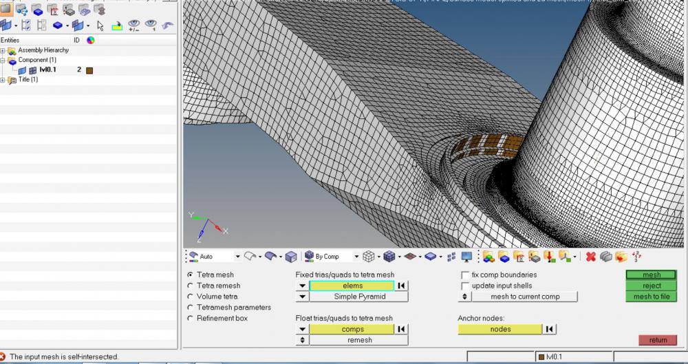
Guys here i try to mesh a 3D model file and for which i made the 2D mesh on the surface using surface deviation with max min element size and growth rate. then i try to make tetrahedral mesh so i went to 3d-----> tetmesh and selected the 2D elements and gave simple pyramid and meshed it. But while the mesh was on progress error was coming as Input mesh is self intersecting and the mesh formed is only over the surface and it is formed as a seperate CFD trias.........


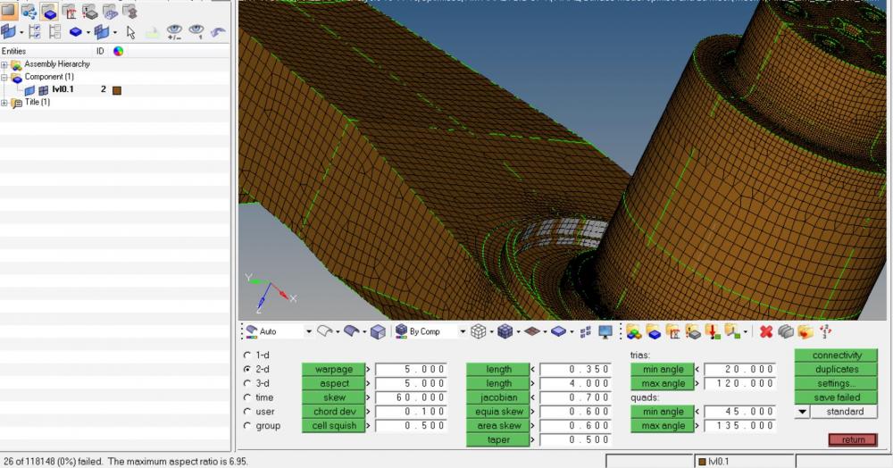
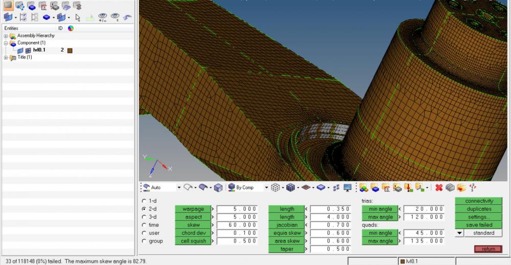
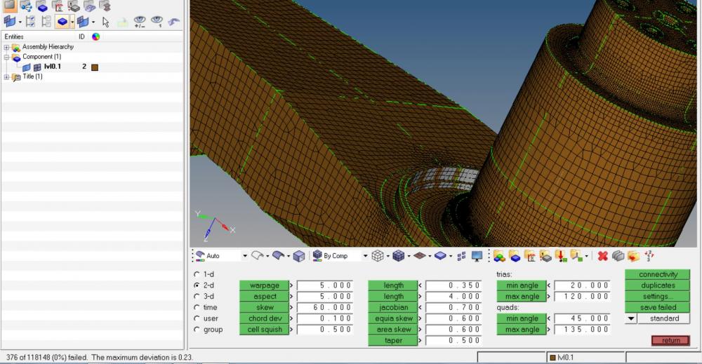
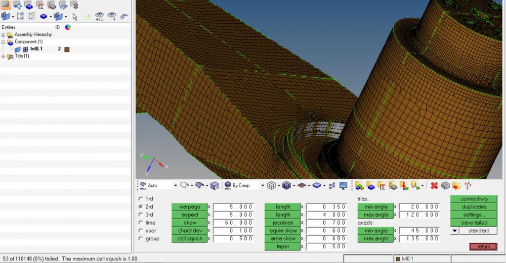
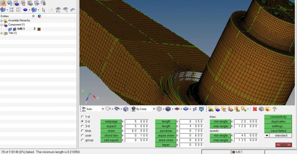
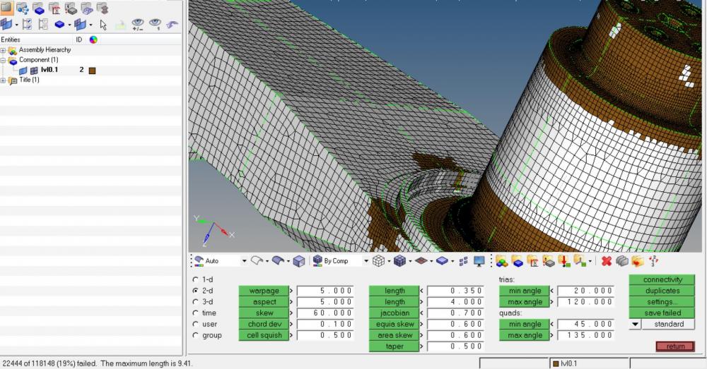
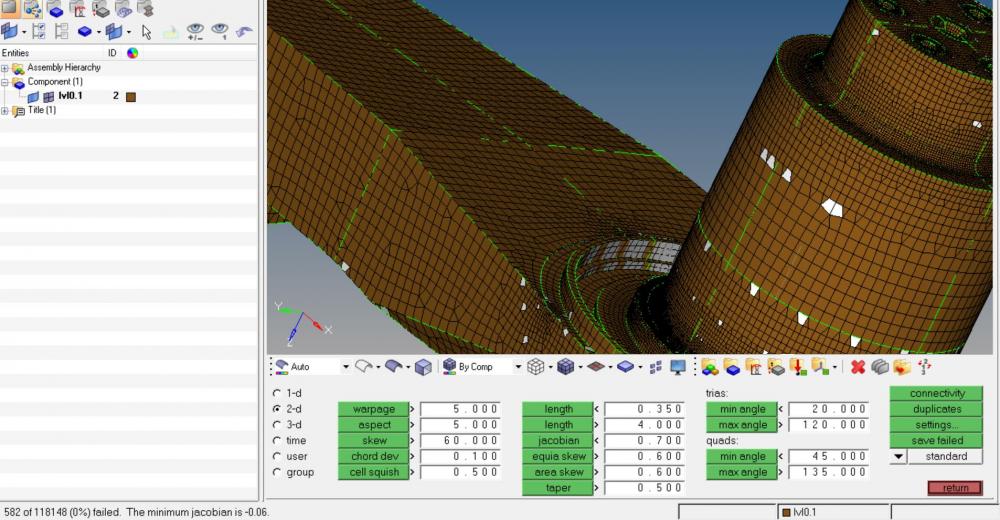
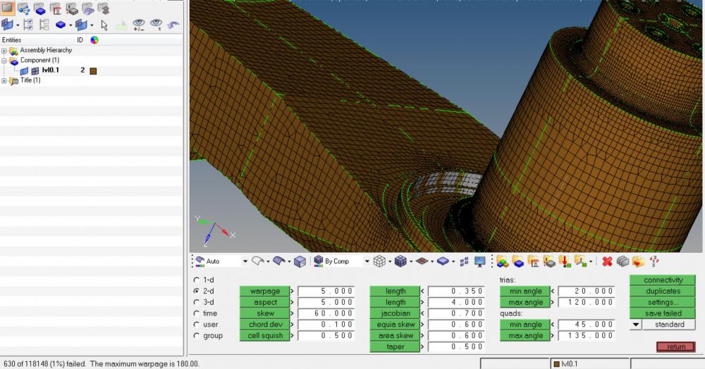
here i have uploaded the snap shot of 2D mesh and corresponding percentage of failure in different 2D mesh checks......from 1 to 8 PICTURE denotes the element check from WARPAGE to JACOBIAN.


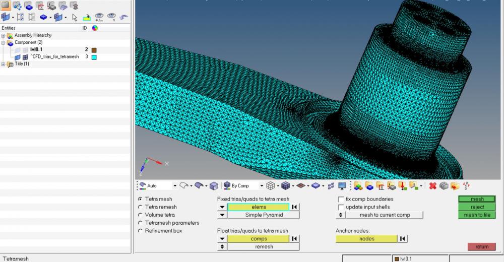
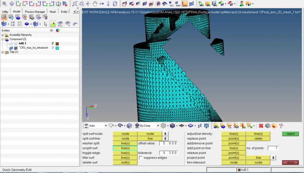
CFD tria PICTURE shows the mesh formed by wen tat mesh was given.


mesh formed over surface alone PICTURE shows the masked view of the inner Cross section


self intersecting PICTURE shows the error msg


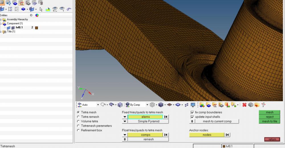
tetmesh  PICTURE shows the options selected for tet mesh and its window

<?xml version="1.0" encoding="UTF-8"?>1.JPG
<?xml version="1.0" encoding="UTF-8"?>2.JPG

<?xml version="1.0" encoding="UTF-8"?>3.JPG

<?xml version="1.0" encoding="UTF-8"?>4.JPG

<?xml version="1.0" encoding="UTF-8"?>5.JPG

<?xml version="1.0" encoding="UTF-8"?>6.JPG

<?xml version="1.0" encoding="UTF-8"?>7.JPG

<?xml version="1.0" encoding="UTF-8"?>8.JPG

<?xml version="1.0" encoding="UTF-8"?>CFD trias 1.JPG

<?xml version="1.0" encoding="UTF-8"?>mesh formed over surface alone.JPG

<?xml version="1.0" encoding="UTF-8"?>self intersecting.JPG

<?xml version="1.0" encoding="UTF-8"?>tet mesh.JPG

Tagged:

Answers

  • QuyNguyenDai
    QuyNguyenDai Altair Community Member
    edited November 2016

    Before do TET meshing, please check carefully your surface mesh. In one of your screenshot, I see you have even negative Jacobian element! TET meshing will be possible when you have a correct & good surface mesh.

  • Altair Forum User
    Altair Forum User
    Altair Employee
    edited November 2016

    Instead of repairing bad elements, create face elements and remove the solid elements.


    Remesh the surface elements and do the tet mesh at the end if you think there is no problem with face elements. 


  • Altair Forum User
    Altair Forum User
    Altair Employee
    edited November 2016

    Nguyen-Dai i have used surface deviation and didnt control the mesh manually....and during 2D mesh i gave min as 0.5 and max as 7 for the element size and growth rate as 1.1......how can i control further more.....should i be reducing the max limit further more.....and how to avoid the negative jacobian....and while going for the tet mesh i found this element being highlighted....does this infer any error.....highlighted error attached.....predicted spot highlighted reason.....

    Thanks for ur reply....

    <?xml version="1.0" encoding="UTF-8"?>highlighting.JPG

    <?xml version="1.0" encoding="UTF-8"?>reason..JPG

  • Altair Forum User
    Altair Forum User
    Altair Employee
    edited November 2016

    as u can see the reason that there is no node connectivity so i splitted the element so that it forms a node connectivity to the nearby node.......and now am running tet mesh....wil update the failure/ successful mesh once its finished.......thanks


  • Altair Forum User
    Altair Forum User
    Altair Employee
    edited November 2016

    @Prakash Pagadala: thanks for ur suggestion........i tried repairing the element but nothing was fruitful and finally deleted the mesh and remeshed it again and now the 3D elements are formed properly.....thanks guys @prakash pagadala and @Q.Nguyen-Dai for ur reply....


    Then the tet mesh formed has a 2% Tet collapse but jacobian is good......is it ok to neglect and continue with the analysis or should i go for further fine tuning of the mesh......