Improve optimization results

Altair Forum User
Altair Forum User
Altair Employee
edited October 2020 in Community Q&A

Dear Optistruct users,


Currently I am using optistruct in order to optimize a bridge type structure. The objective is to minimize the compliance with a volumeconstraint of 25% of the design volume. I have used a one plane symmetry and after 250 iterations I obtained the following result. To prevent the generation of disconnected sections, I increased the maximum amount of iterations and lowered the object tolerance for the relative convergence criteria. However this had no result. I also have applied a symmetry plane but from the results you can see that the structure not exactly symmetric. Can someone help me to improve my results? your feedback will be highly appreciated.
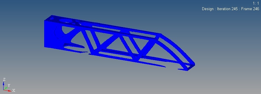
 

Bridge.jpg.4e7aad1ba6b1b7a7f4fb5276988434ca.jpg


Regards,
Michael

Answers

  • Altair Forum User
    Altair Forum User
    Altair Employee
    edited May 2018

    Hi @michaelv


    Did you try to change the ISO value in HV?


    Anyways, you can use OSSmooth to connect the missing material in between.


  • Altair Forum User
    Altair Forum User
    Altair Employee
    edited May 2018

    Dear Prakash,


    Yes I have changed the iso value in hyperview, but I still have disconnected areas. I have increased the amount of iterations and lowered the convergence criteria but still the solver stops prematurely with the notification: OPTIMIZATION HAS CONVERGED. FEASIBLE DESIGN (ALL CONSTRAINTS SATISFIED).  I don't understand why this is happening.

    I also don't like the amount of material located at the origin of the bridge. Should I decrease my volume constraint in order to reduce the amount of material here?


    Regards, Michael

  • Altair Forum User
    Altair Forum User
    Altair Employee
    edited May 2018

    @michaelv


    Do you have any min and max member size constraints?


    If not can you add and check the results? 

  • Altair Forum User
    Altair Forum User
    Altair Employee
    edited May 2018

    Dear Prakash,


    Sorry for my late response, I have tried to use the maximum member thickness for the topology optimization process.

    Unfortunately it resulted in a more dispersed and disconnected solution. I also reduced my volume constraint in order to make the boundary conditions more strict.

    This was the result of the optimization run.


    result1.jpg.952fde83ba03c1ac500a9840156bb832.jpg


    After 150 iterations it converged to this shape and after 287 iterations the optimization process was terminated. I am still not satisfied with this result.
    Do you have any suggestions to improve this result? Currently I am simplifying my model in order to decrease the run time and the required amount of iterations.


    Regards, Michael

  • Altair Forum User
    Altair Forum User
    Altair Employee
    edited May 2018

    Hi @michaelv


    can you share the model file, please?


    Please use the file transfer link in my signature to share the model file

  • Altair Forum User
    Altair Forum User
    Altair Employee
    edited May 2018

    Dear Prakash,


    Thanks for your reply, I have send the model file to your transfer link,


    Kind regards,
    Michael

  • Altair Forum User
    Altair Forum User
    Altair Employee
    edited May 2018

    @michaelv


    OK, thank you. I will get back to you soon. 

  • Altair Forum User
    Altair Forum User
    Altair Employee
    edited May 2018

    Dear Prakash,


    Did you had any time to look at my model? I have tried to simplify my model but it had no improvements.

    I am a little bit stuck right now, do you have any suggestions for me?


    Kinds regards,

    Michael

  • Altair Forum User
    Altair Forum User
    Altair Employee
    edited May 2018

    Hi @michaelv


    Sorry for a late reply,


    I have started looking into the model, I included a couple of manufacturing constraints to check the outcome. I will share the results soon. 

  • Altair Forum User
    Altair Forum User
    Altair Employee
    edited May 2018

    @michaelv


    This is what I got so far but came out without success...

    <?xml version="1.0" encoding="UTF-8"?>MV1.PNG

  • Altair Forum User
    Altair Forum User
    Altair Employee
    edited May 2018

    Dear Prakash,


    Thanks for your reply. Could you share the model with me so that i could have a look?

    I'm interested in the manufacturing constraints that you have applied. That last days, I performed multiple runs but unfortunately without any improvements.

    But my results are different from the results that you obtain.


    Kinds regards

    Michael

  • Altair Forum User
    Altair Forum User
    Altair Employee
    edited May 2018

      Hi @michaelv


    I shared a model file with you, Please try and check the results,


    You may see few disconnected memebers, don't worry, change the ISO value and everything should be fine,


    You can also use OSSmooth to connect the disconnected areas. 

  • Altair Forum User
    Altair Forum User
    Altair Employee
    edited May 2018

    Dear Prakash,


    Thanks for your response, I really appreciate it. I received the files that you send me.

    I will run the optimization, check the results and let you know.


    Kind regards,

    Michael

  • Altair Forum User
    Altair Forum User
    Altair Employee
    edited May 2018

    @michaelv


    Please run the model and check the results,

  • Altair Forum User
    Altair Forum User
    Altair Employee
    edited May 2018

    Dear Prakash,


    I have performed multiple runs but I had to remove one symmetry plane due to the fact that the structure is only symmetric in the Z-X plane.

    After 50 iterations I obtained the following result. 

    optresult.jpg.865136a5aa67db16d7ff38dbb7cee988.jpg


    I used one symmetry plane, Minimum and maximum member size constraints and a minimum gap size. The load paths are clearly visible, but still there is a lot of material located at the left side of the structure. It looks like the maxdim constraint has no effect, due to the fact it is not directional. Therefore the maximum thickness constraint is satisfied due to the thickness of the design domain. I can lower the values but it is not recommended due to the mesh size. Unfortunately I cannot decrease my mesh size due to the restrictions of the student version. When I lower the constraint on the allowable volume it will probably end up with disconnected areas. Which step should I take in order to improve my result?


    Kind regards,

    Michael

  • Altair Forum User
    Altair Forum User
    Altair Employee
    edited May 2018

    Hi @michaelv


    Yes, in some cases MAXDIM may not show its effect,


    From Opti help:

    It is to be noted that use of the maximum member size control induces further restriction of the feasible design space and should therefore only be used when it is truly desirable. Also note that this feature is a new research development, and the techniques are still undergoing improvement. An undesired side effect that has been noticed for some examples is that it might result in more intermediate density in the final solution. Therefore, it is recommended that this feature be used sparingly until the technology becomes more robust.

    While MAXDIM also enforces a spacing of members of the same dimension, the maximum reachable volume fraction is 0.5. For problems involving constraints on structural responses, this could interfere with constraint satisfaction. It is strongly recommended that the behavior of the design problem be studied without MAXDIM first in order to determine if the use of MAXDIM would be advantageous and if the target volume allows for it to be applied.

  • Altair Forum User
    Altair Forum User
    Altair Employee
    edited May 2018

    Hi 


    Thanks for the provided information. It is true that the max member size control has no effect in this situation. Therefore I performed a run without maxdim and lowered the objective criteria and increased the amount of iterations, In order to obtain a well converged solution. With the objective set to minimize the compliance with a volume constraint of 25%, I obtained the following result:


    Optimization1.jpg.3f272967bb7b344b161f0088c91e42f6.jpgOptimization2.jpg.bea953bbbb7e7833823f039df14c089b.jpg


    This is an interesting result and shows clearly the loadpaths in the design but it still consists of disconnected areas. Lowering the ISO value further, results in a blurry and scattered solution. From a structural point of view, I would suggest that material should be present at these disconnected areas in order to maximize the stiffness of the structure. Now when a load is acting on the structure, the load is transferred by bending stresses instead of tensile and compressive stresses, which is less efficient and not beneficial for the compliance of the structure. So my question is, what is the reason for this effect? Does this mean that the solution is still not converged? I am looking forward to your response.


    Regards,
    Michael

  • Altair Forum User
    Altair Forum User
    Altair Employee
    edited May 2018

    Hi Michael,


    Solver provides converged solutions based on the error tolerance, objective and constraints. If they are satisfied solver comes out with a feasible design.


    This doesn't mean that one has to go with the design predicted at the last iteration, 


    Since there was a difference in the tolerance and the results are within the tolerance (assuming) you got such a result. 


    Solution 1) You can take the design as it is and modify in such a way that it is manufacturable and re-analyze

    Solution 2) check for intermediate design iteration and take that design, re-analyze and check the results, 

  • Altair Forum User
    Altair Forum User
    Altair Employee
    edited May 2018

    Dear Prakash,


    Thanks for your response, I have checked the convergence history and noticed that the constraints are not satisfied for a long time. This can be seen in the animation.

    You are right, the best design can be found in the intermediate design iterations. I have rerun the optimization and used the SHRES option to obtain an .sh file for each particular iteration. Now I can select a preferred iteration which is suitable for post-processing. Thanks for sharing your knowledge.


    Kind regards,
    Michael


  • Altair Forum User
    Altair Forum User
    Altair Employee
    edited May 2018

    @michaelv


    Success... :)/emoticons/default_smile.png' srcset='/emoticons/smile@2x.png 2x' title=':)' width='20'>