Hello,
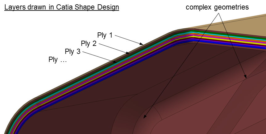
I’ve the task to build a ply-based solid composite model. The tricky part is, I have to build the model out of plies, which are drawn in Catia Shape Design (see picture 1).
Why do I want to model each layer as a solid (ply-based solid composite model)?
- First reason, the composite part is used in a load introduction area. From the literature, a solid design is recommended.
- Second reason, I want to make use of Altair MultiScale Designer (MSD). In Optistruct only solid elements are currently supported with user materials. Therefore I use MAT9ORT as material. In the last step I replace the material information with an user defined material (woven 5 harness satin), which I get from the MultiScale Designer (MSD).
Why is the composite part drawn in Catia Shape Design?
- Since the design of the composite part is complex at many points, Catia Composite Design (CPD) couldn’t be used for that. Instead the whole composite part is drawn in Catia Shape Design. Each layer (=ply) is drawn individually. So the geometrical informations I get from the CAD model are correct. But I have to work with this model and cannot rebuild it in CPD.
What I've tried so far:
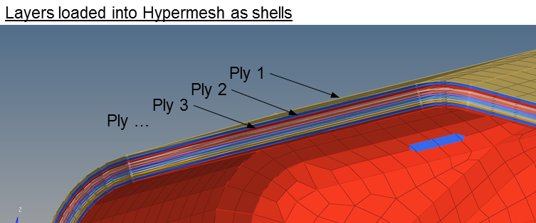
- I loaded each layer into Hypermesh and meshed the components (automesh, quads only). Then I created the materials (MAT9ORT), the plies (PLY01, ...), a laminat stacking and properties. Last I would do a shell to solid conversion. (see picture 2)
Problems and questions:
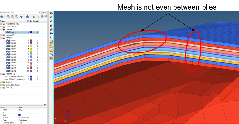
- The layers don’t know each other. So the mesh of each layer is different. (see picture 3)
- Moreover in the thickness direction of the plies, they are not really connected. (see picture 3)
- Can you help me to find a strategy to build up the laminate out of the shapes I have from Catia?
Since I’m an unexperianced HM user, I kindly ask you to explain your help and instructions in detail.
Thanks a lot!
My software:
- Hypermesh 2017.2
- OptiStruct as Solver
- Multiscale Desinger 3.4 for the user material
- Catia V5
<?xml version="1.0" encoding="UTF-8"?>
<?xml version="1.0" encoding="UTF-8"?>
<?xml version="1.0" encoding="UTF-8"?>