Composite Steel Design in S-FRAME/S-STEEL
Composite steel beams utilize the compressive strength of concrete in tandem with the tensile strength of steel to facilitate efficient, yet structurally sound designs. When designed correctly, composite steel beams can offer longer beam spans, reduced steel beam sizes, and less deflection compared to standard steel beams. Engineers must carefully consider both pre-composite, and composite loading conditions for serviceability and ultimate limit states to ensure the underlying beams, shear connectors, camber, and more are sufficient for code requirements.
Altair S-FRAME utilizes a staged construction approach to allow for the design of shored, and unshored composite floor systems that consider pre-composite, and composite behaviour. This approach offers several advantages including the consideration of continuous composite steel beams, with negative moments, and the ability to consider Gravity and Lateral Analysis in a single model. This allows users to design continuous girders that support secondary floor beams, rather than simplifying them to simply support spans. Additionally, users can review results for Gravity, and Lateral Analysis of composite beam systems within the same model, regardless of complexity.
S-STEEL will determine the number of shear studs required for the desired percentage of shear transfer between the steel deck, and steel beam, and report this information both graphically and numerically.
During the modeling process, the effective widths of both interior, and exterior beams are automatically calculated as per code requirements. These calculations also consider openings, and overhangs in the floor system. Beam camber requirements are also determined and reported both graphically and numerically.
The high-level workflow is described below:
- Build Model
- Size Sections for Composite Loading
- Reanalyze
- Evaluate Pre-Composite performance – Determine Camber
- Reanalyze
- Final Code Check
Below is some further elaboration on each of these steps:
Building of Analysis Model
- Construct or Import your S-FRAME model just as you would any other model.
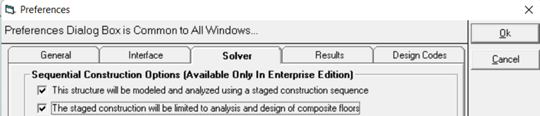
- Enable the following settings in the Settings Menu > Preferences. Note: This setting enables both a pre-composite and composite stage in your model. At this point, the two stages will be identical.
-
- Use the Area Load Span Directions to automatically compute composite beam effective widths. Floor openings considered using Hole Panels.
- Create Load Combinations for Pre-Composite and Composite Ultimate Limit State (ULS) and Serviceability Limit State (SLS) conditions.
-

-
Size Sections for Composite Loading
- Use S-STEEL to initialize the Composite Stage and size the steel sections for their Ultimate Limit State Loading, and composite deflection requirements.
-

- Upon completion of this design iteration, the optimized steel sections are determined, and S-STEEL calculates the number of required shear studs for each segmented portion of the girder. Steel stud requirements and stud spacing account for situations where a beam may support decks spanning in different directions.
-
Reanalysis of Model
- After steel sections are optimized, S-FRAME will automatically update the pre-composite, and composite stage members. The composite stage section, however, will reflect the increased strong axis moment of inertia due to the contribution from the hardened concrete floor. The section properties are influenced not only by the decking, and slab, but also the shear studs provided.
- A second structural analysis must occur due to the change in section for both the pre-composite and composite stage affecting the stiffness.
-
Evaluate Pre-Composite Performance and Determine Camber
- Establish camber requirements for unshored composite floor systems (for shored systems, this step is usually not required).
-

- Pre-camber SLS loads used to determine camber requirements.
- Camber assigned to each composite beam based off user preferences
- Net deflection is based off residual camber, and composite SLS deflections
- Code check also ensures pre-composite floor system can support ULS factored Load Combinations.
- Camber limits are specified for chosen beams, and camber is reported graphically, and numerically.
- A final design optimization is performed on the composite load combinations to optimize steel members.
-

-
Reanalysis of Optimized Structure
- Upon completing the automated design, S-FRAME will issue a warning if the model has changed. If a change in section sizes occurred, a reanalysis should be performed on the updated steel members.
-
- Final Code Validation Check
- One final code validation check is performed on the composite stage to ensure that all members pass strength and serviceability requirements.
-
- Users can generate Engineering Design Reports for the Composite Stage, which will include the ‘Pre-Composite Moment Capacity Checks, as well as Camber information, Stud Layout, and more.
-
-
-

-
At this point, users would be able to perform both a gravity, and lateral analysis on the structure. Users have the option to select which stage (Pre-composite or Composite) they would like to analyze for non-staged construction analysis. During the process of round-tripping back to S-FRAME, your composite section’s analysis section inertia will be automatically computed per code requirements.
For more information on Composite Steel Design in S-FRAME, you can find a webinar recording on the subject here. More information on Steel Design can also be found on the Altair How To Youtube Channel. Feel free to reach out to us if you have any questions.
